Soil bioengineering works
Timber soil bioengineering works, such as the live crib wall (single or double), are modelled in the Slope/MRE module as a reinforced earth whose reinforcements are timber logs: bar elements with a circular section and the Wood material. The module runs the internal checks (pull-out and breakage of the logs) and the global checks (overturning, sliding, bearing capacity). The structure is then passed to Slope for the global stability check of the slope.
In short
In the Reinforcement typology archive create a new reinforcement with Type = Bars and material Wood, and assign its diameter and the wood strengths. Then select the reinforcement in Position of the reinforcements to generate the logs.
1. General data
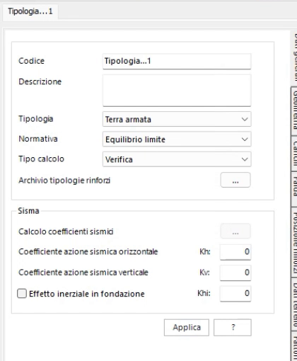
In the General data tab of the typology choose Typology Reinforced earth (Terra armata), Standard Limit equilibrium and Calculation type Verification (see General data). If the structure is in a seismic area, also assign the Kh and Kv coefficients here.
2. Geometry of the crib wall
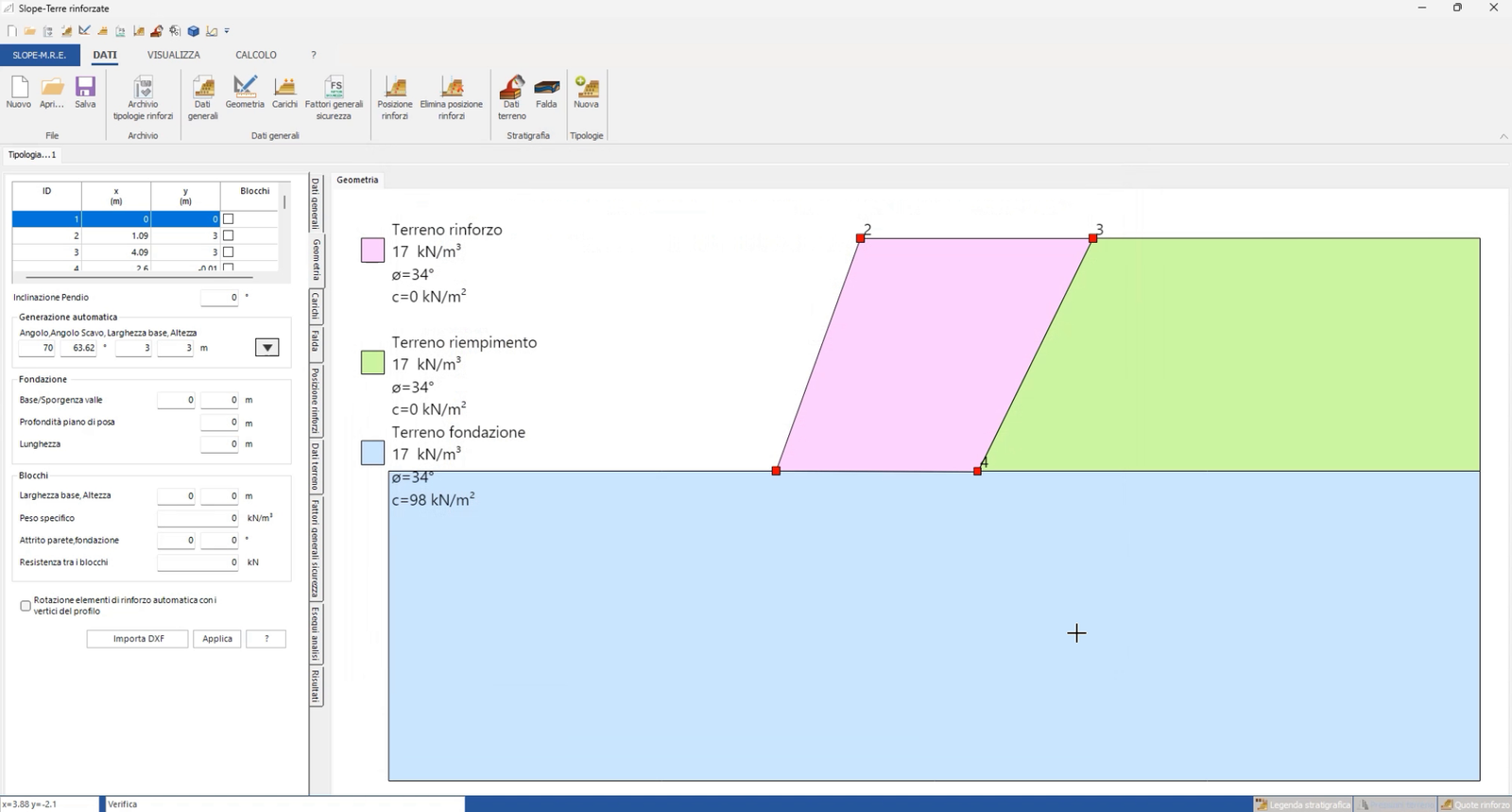
In the Geometry tab (Geometrical data) define the body of the crib wall with the Automatic generation. Enter the face Angle, Excavation angle, Base width and Height, then press Apply. In the example they are 70°, 63.62°, 3 m and 3 m. Three zones are created, each with its own soil parameters:
- Reinforced soil: the fill of the crib wall, between the logs;
- Backfill soil: the soil behind the structure;
- Foundation soil: the bearing soil.
3. Defining the timber log in the Reinforcement typology archive
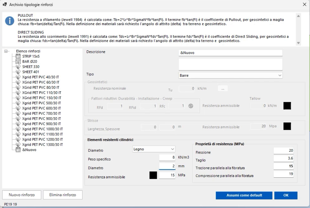
From the DATA ribbon open the Reinforcement typology archive. In the Reinforcement list right-click and choose New reinforcement (or press the New reinforcement button at the bottom), then:
- in Description give the reinforcement a name (for example Timber log Ø200);
- in Type choose Bars. The Cylindrical resisting elements frame becomes active;
- in the first drop-down list of the frame choose the material Wood;
- assign the Unit weight (8 kN/m³ in the example) and the Diameter of the log in mm (200 mm in the example);
- fill in the Strength properties (MPa) of the wood: Bending, Shear, Tension parallel to the grain and Compression parallel to the grain. In the example they are 20, 3.6, 15 and 19 MPa. Also check the Allowable strength of the log (15 MPa in the example);
- confirm with OK.
Wood values
The values in the example are only indicative. Assign the strengths of the strength class of the wood actually used (for example from EN 338 for solid timber), reduced with the factors required by the design standard.
4. Position of the logs
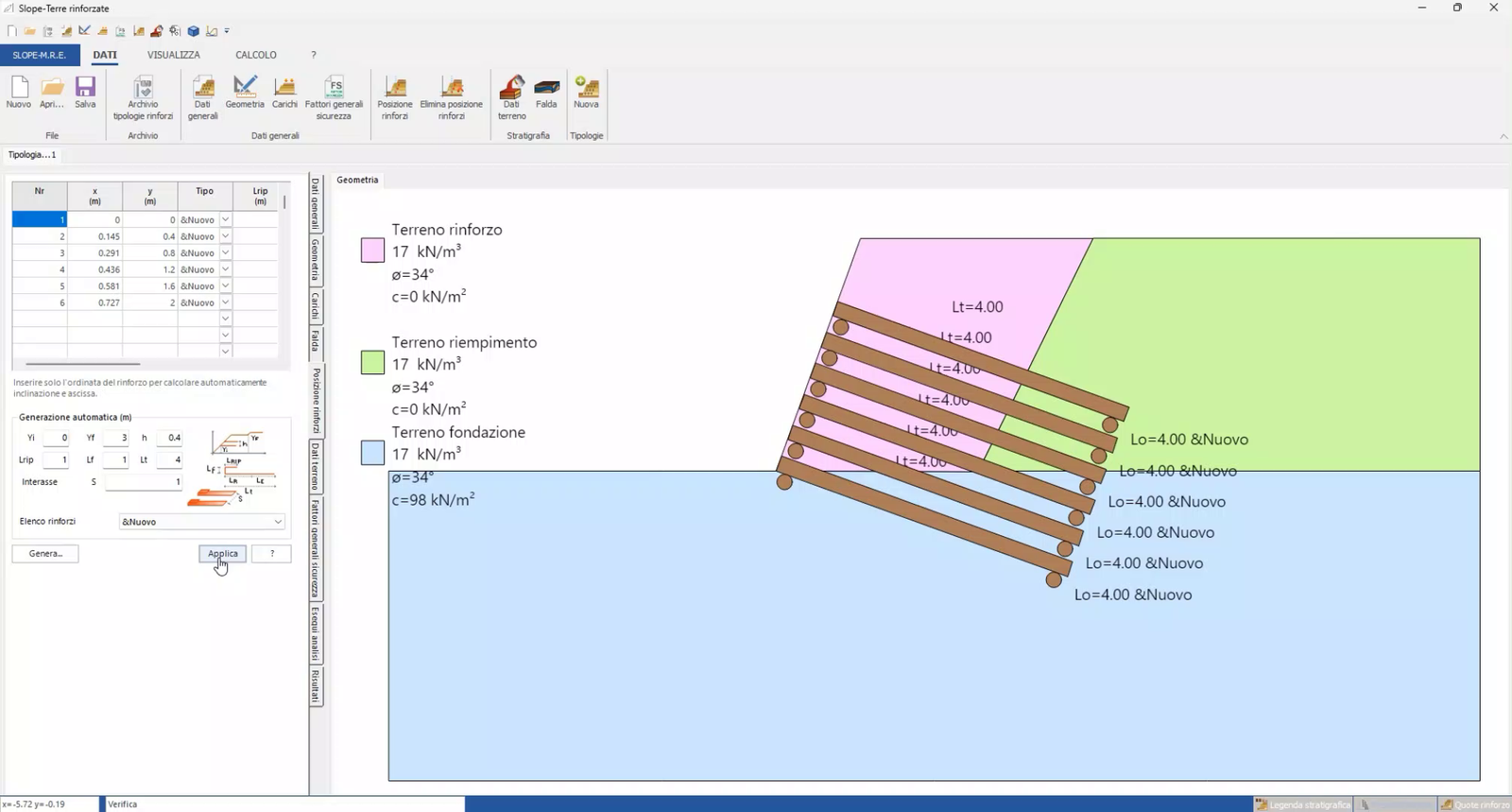
In the Position of the reinforcements tab (Position of the reinforcements) fill in the Automatic generation (m):
- Yi, Yf: level of the first and of the last log (0 and 3 m in the example);
- h: vertical spacing between the logs (0.4 m);
- Lrip, Lf, Lt: folding length, face length and total length of the log (1, 1 and 4 m);
- Spacing S: horizontal spacing of the logs (1 m);
- Reinforcement list: the timber log just created.
Press Generate…. The insertion points appear as red dots on the face and their coordinates are listed in the table.
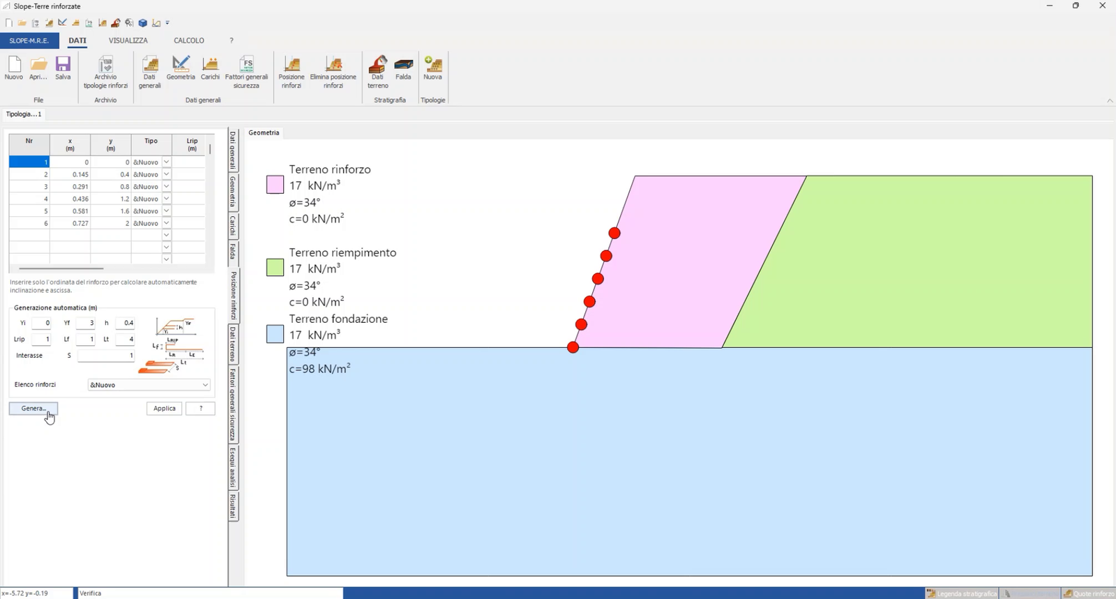
Then press Apply. The dots are replaced by the timber logs.
5. Calculation in the MRE module
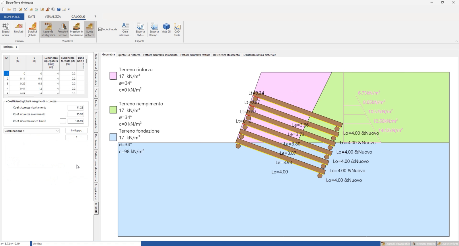
From the CALCULATION ribbon press Run analysis. The Results tab shows the global safety factors (overturning, sliding, bearing capacity) for the selected combination. The drawing tabs show the thrust on the reinforcement, the pull-out and breakage safety factors, the pull-out resistance and the ultimate strength of the material. For details see Results and Global verification.
6. Global stability in Slope
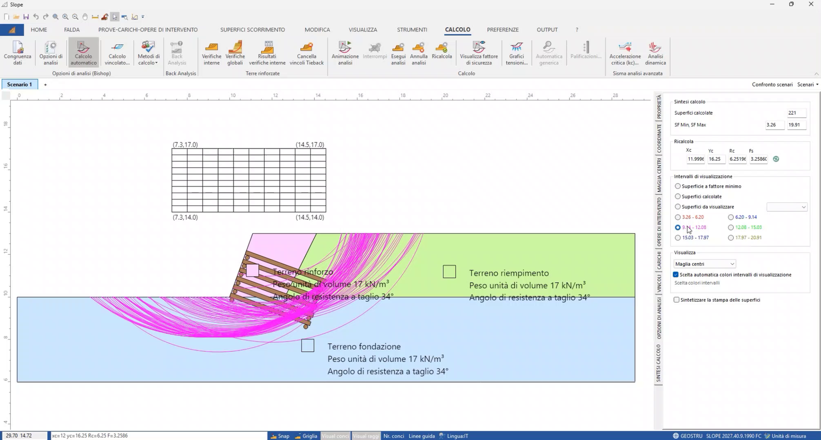
Close the module from SLOPE-M.R.E. → Exit. The crib wall is brought back into the Slope profile together with the timber logs. From CALCULATION → Calculation methods choose the method (for example Bishop) and start the Automatic calculation. The minimum safety factor takes into account the logs crossed by the slip surfaces.
Driven timber piles
This page covers crib walls with horizontal logs. For timber piles driven into the slope use the Pilings instead, with the shear stress method and the shear strength of the wood.
The screenshots show the Italian interface of the program.