Three-stage rapid drawdown
The Three-stage rapid drawdown window checks the stability of the upstream face of dams, levees and banks when the water level drops quickly. The method is that of Duncan, Wright and Wong (1990), adopted by the USACE manual EM 1110-2-1902.
Watch the video
This window is explained box by box in the "Rapid drawdown" chapter of the video tutorial Seepage, pore pressures and rapid drawdown.
Activated version
The three-stage rapid drawdown check is available in the activated version of Slope. A project with rapid drawdown on, opened in the non-activated version, is computed without drawdown.
Why rapid drawdown is critical
With a full reservoir the water pushes on the upstream face and supports it. When the reservoir is lowered quickly that support is gone, but the soil of the face stays saturated: in low-permeability materials the water has no time to leave. The soil responds undrained, with a strength that depends on the stresses reached with the full reservoir. For the upstream face this is usually the most severe condition.
Simply lowering the water table and running a drained analysis is not enough: it ignores the undrained response of the soil. The three-stage method accounts for it.
The method: three stages
For each surface the slice computation is repeated three times.
Stage 1 – full reservoir. Active water table (and the pore pressure grid, if any, for example from seepage), drained parameters c', φ'. From the solution Slope gets, for each slice, the consolidation stresses on the failure plane:
Stage 2 – after drawdown, undrained. Water table after drawdown. In materials with impeded drainage the strength is undrained (φ = 0) and equals τff, interpolated by the consolidation ratio Kc between two envelopes:
- the envelope for Kc = 1 (isotropic consolidation): intercept d and angle ψ, from consolidated undrained (CU) triaxial tests;
- the envelope for Kc = Kf (consolidation at failure): the effective envelope c', φ'.
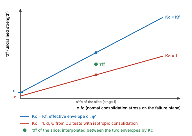
The other materials keep c', φ' with the pore pressures of the water table after drawdown.
Stage 3 – drained strength where lower. In the slices where the drained strength, computed with the normal stresses of stage 2, is lower than τff, the drained strength is used and the surface is computed again.
The factor of safety of the surface is the minimum of stage 2 and stage 3. If F1 < 1 already, the slope is unstable with a full reservoir and the result is F1.
Step by step
The example is the Earth dam template with the default values, the seepage grid active and only water table 1 (full reservoir at elevation 58.5 m).
-
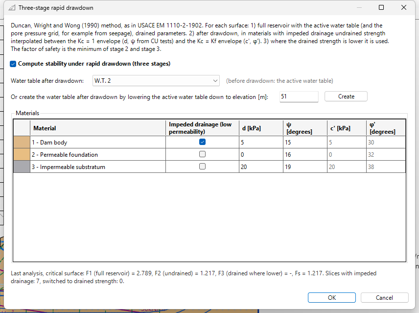
WATER TABLE tab → Pore pressures group → Rapid drawdown. The Three-stage rapid drawdown window opens; at the top is the description of the method.
-
Tick Compute stability under rapid drawdown (three stages). From now on F5 and Recompute use the three-stage method.
-
Water table before and after drawdown. The water table before drawdown is always the active one. For the water table after drawdown you have two ways:
- choose another water table already drawn in the Water table after drawdown list;
- or type an elevation in Or create the water table after drawdown by lowering the active water table down to elevation and press Create: Slope creates a new water table equal to the active one, cut at that elevation, and selects it as the water table after drawdown.
If the project has only the active water table, the list says No other water table: create it below with Create. The proposed elevation is the lowest point of the ground profile.
Elevations are absolute, as in the rest of the project. In the example the base of the dam is at 50 m: type 51 (1 m of water above the base, reservoir almost empty) and press Create. W.T. 2 appears in the list. When you reopen the window, the elevation field shows the level used by the last Create.

-
Materials. One row per layer:
Column Meaning Impeded drainage (low permeability) the material does not drain during drawdown: it uses the undrained strength of stage 2 d [kPa], ψ [degrees] envelope for Kc = 1 from CU tests: τff = d + σ'fc·tan ψ c', φ' [degrees] effective parameters of the layer, in grey: read from the Geotechnical properties, they give the envelope for Kc = Kf Slope proposes Impeded drainage for permeable materials with kh ≤ 1E-6 m/s (the seepage permeability), d = c' and ψ = φ'/2. These are starting values: replace them with the test results. In the example the dam body (kh = 1E-7) has impeded drainage with d = 5 kPa and ψ = 15°; foundation and substratum stay drained.
-
Press OK. The GWT list of the WATER TABLE tab now holds water tables 1 and 2; the active one is still 1 (full reservoir).
- Press F5 (COMPUTATION → Perform analysis). Slope repeats the three stages for every surface of the grid.
- Reopen Rapid drawdown to read the results of the critical surface (see below).
Results

At the bottom of the window:
Last analysis, critical surface: F1 (full reservoir) = 2.789, F2 (undrained) = 1.217, F3 (drained where lower) = -, Fs = 1.217. Slices with impeded drainage: 7, switched to drained strength: 0.
| Value | Meaning | Example |
|---|---|---|
| F1 (full reservoir) | factor of safety of stage 1 on the critical surface | 2.789 |
| F2 (undrained) | stage 2, after drawdown with undrained strength | 1.217 |
| F3 (drained where lower) | stage 3; "-" means no slice switched to drained strength, so stage 3 was not needed | - |
| Fs | minimum of stage 2 and stage 3: the result of the check | 1.217 |
| Slices with impeded drainage | slices of the surface lying in materials with impeded drainage | 7 |
| switched to drained strength | slices where stage 3 used the drained strength | 0 |
The critical surface moves to the upstream face (centre 65.35; 84.07, R = 34.42 m): in the Earth dam template the factor of safety drops from 1.36 (full reservoir, critical surface downstream) to 1.22 after rapid drawdown. F1 = 2.789 shows that with a full reservoir the same upstream surface is very safe: the drawdown is what makes it critical.
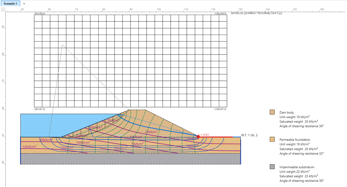
The same values are in the calculation report, with the description of the method and the water tables before and after drawdown. Surfaces where a stage has no valid solution (method not converging or non-physical numerical solution) are discarded and do not take part in the search for the minimum.
To go back to the normal analysis (full reservoir), untick the box of step 2 and press OK.
Instantaneous rapid drawdown and lowered water table
| Analysis | What it does | When to use it |
|---|---|---|
| Three-stage method (this window) | undrained strength in materials with impeded drainage, from the stresses with full reservoir | checking dams, levees and banks |
| Rapid drawdown (instantaneous) (menu of the recompute button in the Recompute panel) | recomputes one surface as if the external water were removed at once: slices previously submerged use the saturated weight, without the external water thrust, and keep the water table pore pressures; no distinction between drained and undrained materials | quick, very conservative check of a single surface |
| Lowered water table (water table after drawdown made active, normal analysis) | drained analysis with the final level | long-term condition, slow drawdown; it does not represent rapid drawdown |
The instantaneous method cannot be combined with the three-stage method: when the three-stage method is active, the instantaneous one is excluded.
Validation
The method was compared with a published reference case: the zoned Johnson Reservoir dam, with a clay core, drawdown from 48.77 m to 30.48 m (validation report and files in the Examples\Seepage and Pore Pressures\Johnson Reservoir folder of Slope). Core with impeded drainage, d = 11.97 kPa and ψ = 14°.
| On the reference circle, Spencer method | F1 | F2 = Fs |
|---|---|---|
| Slope | 1.922 | 1.382 |
| Published solution | 2.05 | 1.31 |
| Independent Bishop calculation (full reservoir) | 1.93 | — |
F1 agrees with the independent calculation. The difference in F2 comes mainly from the pore pressures of stage 2: the published solution takes them from a transient seepage analysis, Slope from the water table after drawdown (the usual assumption for free-draining materials; in undrained materials, with φ = 0, the pore pressure plays no role). As in the published solution, stage 3 does not reduce the result.
References
- Duncan J.M., Wright S.G., Wong K.S. (1990). Slope stability during rapid drawdown. Proceedings of the H. Bolton Seed Memorial Symposium, Vol. 2, 253-272.
- Duncan J.M., Wright S.G., Brandon T.L. (2014). Soil Strength and Slope Stability, 2nd ed. Wiley.
- U.S. Army Corps of Engineers (2003). Slope Stability, EM 1110-2-1902.
©Geostru