Soil Nailing
Design method of Soil Nailing system
One of the interventions to stabilize a slope is that of soil nailing.
The sizing of the steel bars (internal verification) is performed assuming attempt dimensions for them and verifying that:
The safety factor (FS) is defined as:
SF = Available force / Force required
To estimate the maximum values of resistance can be used the relations proposed in the literature by Hausmann 1992) and MGSL Ltd (2006).
Maximum allowable tensile strength of the steel bar:
| Ta = (Φ · f y) · (d - 4)2 · π / 4 | Eq ( 5.8) |
|---|---|
where
| Φ | = reduction factor of the stress established by the legislation |
|---|---|
| fy | = steel yield strength |
| d | = steel bar diameter |
Maximum allowable force between steel and mortar:
| [ β (fcu)1/2] · π · (d - 4) · Le / SF | Eq (5.9) |
|---|---|
where
| β | =0.5 for bars type 2 according to Australian standard (imposed by standard) |
|---|---|
| fcu | = compressive strength of concrete at 7 days |
| SF | = adopted safety factor (imposed by standard) |
| Le | = effective length of anchor |
Maximum allowable force between the ground and mortar:
| [(πDC' + 2D Kα σν' tanΦ)· Le] / SF | Eq (5.10) |
|---|---|
where
| D | = diameter of the hole in the ground |
|---|---|
| C’ | = effective cohesion of soil |
| Kα | = coefficient of lateral pressure (α = angle of inclination) = 1 - (α/90) (1-Ko) = 1 - (α/90) (sinΦ) |
| σν' | = effective vertical stress of the soil calculated at the average depth of reinforcement |
| Φ | = friction angle of the soil. |
Example of calculation
Design assumptions
For the critical section of the unstable slope shown in the figure are known the following design parameters:
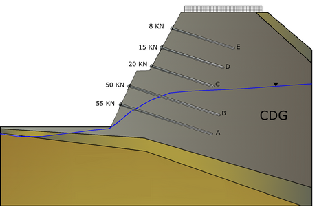
| Soil type | CDG (completely decomposed granite) |
|---|---|
| C ' | 5 kPa, |
| g | 20 kN/m3, |
| φ' | 38° |
| D | 0,1 m, diameter of the holes in the ground |
| a | 15°, inclination angle of the bar |
| gw | 9.81kN/m3, specific weight of water |
| E | 8,0 | 25 | 2 | 4,70 | 3,30 | 8,00 | 16,00 | | D | 8,0 | 25 | 2 | 4,20 | 3,80 | 15,00 | 30,00 | | C | 8,0 | 25 | 2 | 3,70 | 4,30 | 20,00 | 40,00 | | B | 12,0 | 32 | 2 | 3,80 | 8,20 | 50,00 | 100,00 | | A | 12,0 | 32 | 2 | 2,30 | 9,70 | 55,00 | 110,00 |
Design data
The minimum safety factors required by the regulations are given in the table:
| Failure due to tensile stress of the steel bar | fmax=0,5 fy | | Pullout between concrete and steel bar | 3 | | Shear failure of adjacent soil | 2 |
Tensile strength of the steel bar:
fy= 460 Mpa(steel yield strength);
Φ·fy= 0,5 fy= 230 Mpa (maximum tensile stress of steel).
Maximum tensile strength of the steel bar
Ta = (Φ · f y) · (d - 4)2 · π / 4
| Nailing | Bar length (m) |
Bar dimeter (mm) |
Horizontal distance between bars (m) |
Force per meter of length (KN) |
Force required (KN)) |
Maximum allowable tensile force (KN)) |
Check (Ta>Tr) |
|---|---|---|---|---|---|---|---|
| E | 8,0 | 25 | 2,0 | 8,0 | 16,0 | 79,66 | ok |
| D | 8,0 | 25 | 2,0 | 15,0 | 30,0 | 79,66 | ok |
| C | 8,0 | 25 | 2,0 | 20,0 | 40,0 | 79,66 | ok |
| B | 12,0 | 32 | 2,0 | 50,0 | 100,0 | 141,62 | ok |
| A | 12,0 | 32 | 2,0 | 55,0 | 110,0 | 141,62 | ok |
Calculation table of the tensile strength of the steel bar
Pull-out between steel bar and concrete
fcu=32Mpa, cubic strength of mortar at 28 days,
b=0.5 for bars type 2 (deformable),
SF= 3, safety factor
Maximum allowable force between mortar and steel bar:
[ β (fcu)1/2] · π · (d - 4) · Le / SF
Le= effective length of the bar,
| Nailing | Bar length (m) |
Bar diameter (mm) |
Horizontal distance between bars (m) |
Free length La (m) |
Effective length (m) |
Force for meter of length (KN) |
Required force (KN) |
Maximum allowable strength (KN) |
Check (Tmax>Tr) |
|---|---|---|---|---|---|---|---|---|---|
| E | 8,0 | 25 | 2,0 | 4,70 | 3,30 | 8,0 | 16,0 | 205,26 | ok |
| D | 8,0 | 25 | 2,0 | 4,20 | 3,80 | 15,0 | 30,0 | 236,36 | ok |
| C | 8,0 | 25 | 2,0 | 3,70 | 4,30 | 20,0 | 40,0 | 267,46 | ok |
| B | 12,0 | 32 | 2,0 | 3,80 | 8,20 | 50,0 | 100,0 | 680,06 | ok |
| A | 12,0 | 32 | 2,0 | 2,30 | 9,70 | 55,0 | 110,0 | 804,46 | ok |
Calculation table: Check to pull-out of steel bar from mortar
Lack of adhesion between mortar and ground
Tf= (πDC'+ 2DKασv' tanφ) × Le (Mobilized resistance between mortar and ground),
αK = 1 - (α / 90) (1-Kο) = 1 - (α / 90) (sinφ), inclination factor,
Completely decomposed granite (CDG) with Kα = 0.897
Tf = (πDC'+ 2DKασv'tanφ) × Le = (1.571 + 0.14σ'v) × Le= (1.571+ 0.140 σ'v)
| Effective length in CDG layer (m)
Le | Depth of the midpoint of the effective length | | |
| Layer CDG | | | |
| CDG | WATER | | |
| E | 3,30 | 3,40 | 0,00 |
| D | 3,80 | 5,30 | 0,00 |
| C | 4,30 | 7,20 | 0,00 |
| B | 8,20 | 9,70 | 1,40 |
| A | 9,70 | 9,40 | 3,00 |
Calculation table: Geometrical characteristics of steel bars
| CDG | CDG | | | | | | | E | 68.00 | 36.65 | 36.65 | 16.00 | 2.29 | OK | | D | 106.00 | 62.45 | 62.45 | 30.00 | 2.08 | OK | | C | 144.00 | 93.58 | 93.58 | 40.00 | 2.34 | OK | | B | 180.27 | 220.16 | 220.16 | 100.00 | 2.20 | OK | | A | 158.57 | 230.92 | 230.92 | 110.00 | 2.10 | OK |
Calculation table: Check for failure due to lack of adhesion between mortar and ground