Computation of the Yield Moment
Calculation of the Yield Moment for a steel tubular section
The section under examination is the following:
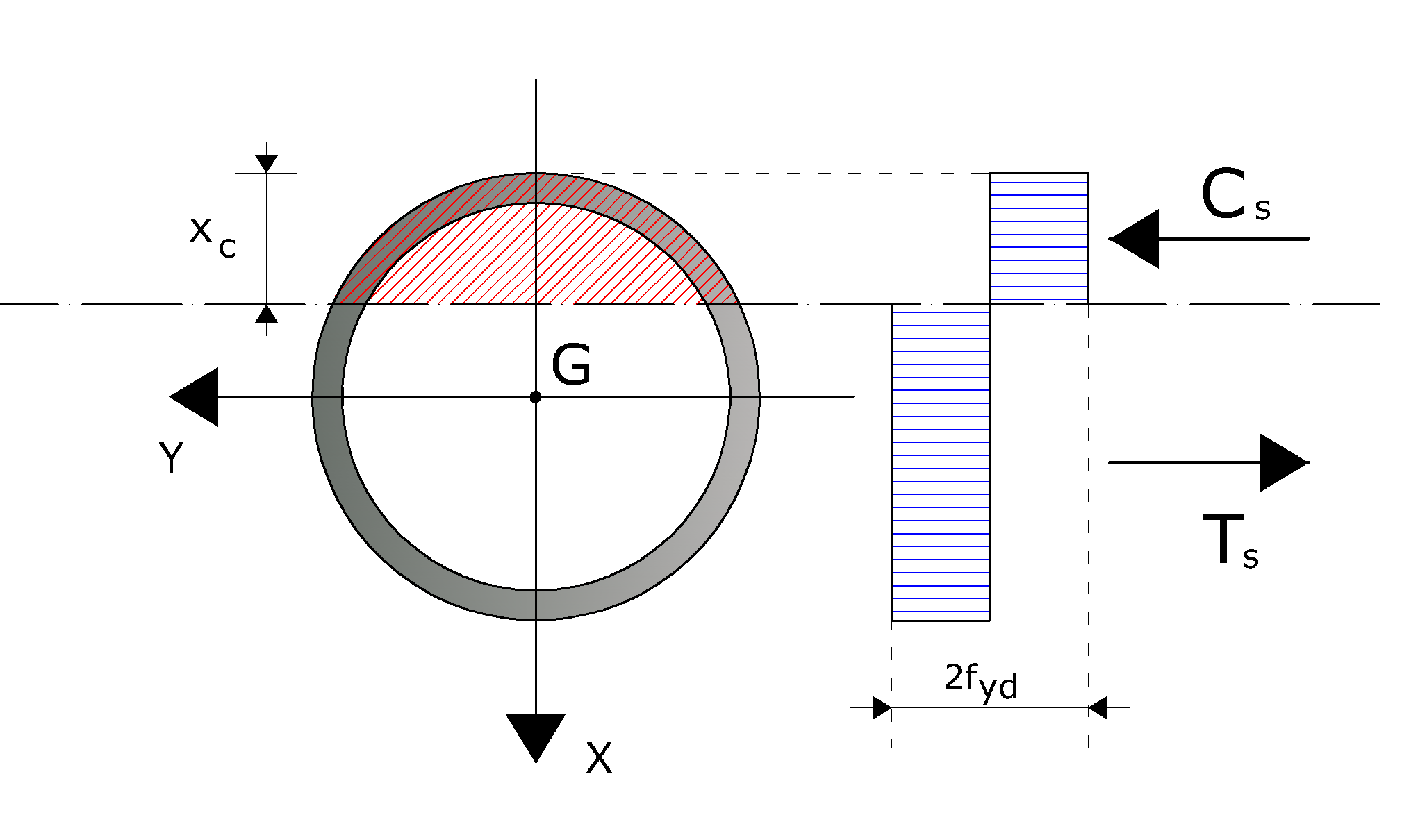
Reference diagram for the calculation of the yield moment for a steel tubular section
The calculation of the yield moment has been made assuming, for steel, a rigid-plastic constitutive bound, with limit yield stress equal to fyd. The field moment has been determined by interpolation on the section interaction curve.
In order to construct the interaction curve of the section, the following procedure has been followed:
- step 1Fixing the depth of the neutral axis (xc) - (starting from xc = 0);
- step 2Calculating the resultant in terms of normal stress (Nd);
- step 3Calculating the resultant moment (Md) as regards the geometric center of gravity of the section;
- step 4Memorizing the calculated point (Nd, Md);
- step 5Increasing xc, if xc is still lower than or equal to the diameter of the section, then back to step 1, otherwise the procedure is over.
 In this way, the upper part of the interaction domain is constructed. In any case the lower part is identical, but heme symmetrical. |
|---|
The generic point of the interaction domain has been calculated using the following formulas:
In the previous formulas, the symbols have the following meaning:
Calculation of the Yield Moment for a steel tubular section immersed into a concrete circular section
The previous formulation, used for the tubular section, can be extended to the case in which the tubular section is immersed into a concrete section. In this case, it is necessary to take into account the concrete contribution, according to the following diagram:
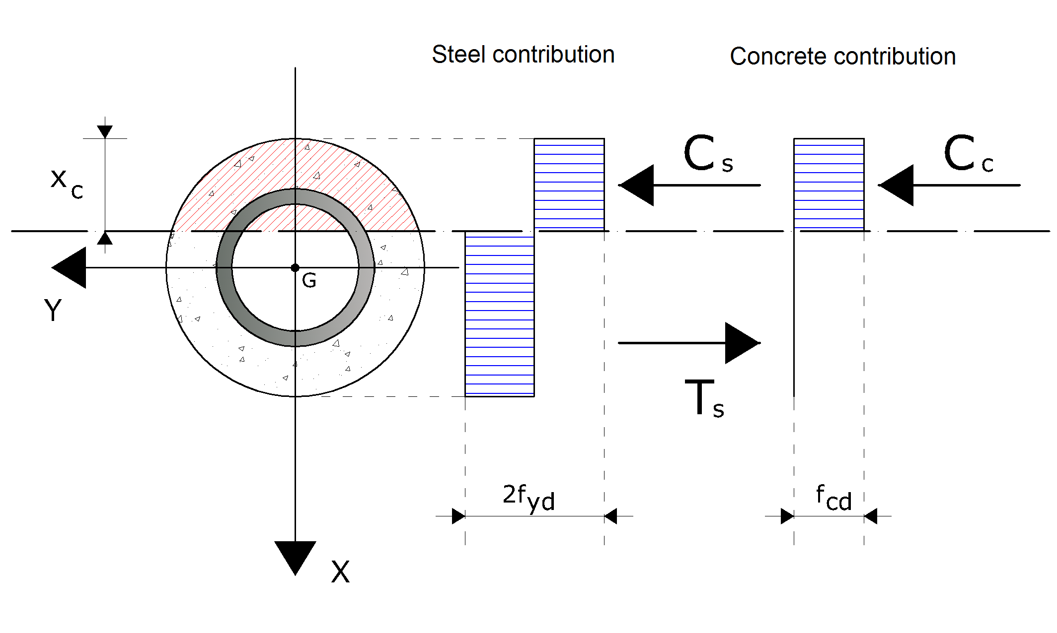
The diagram for the calculation of the field moment for a steel tubular section immersed in a circular concrete section
As you can observe, the concrete type considered as a reactant is only compressed concrete. The values of the stresses at a fixed depth of the neutral axis of the section is as follows:
In the previous formulas, the symbols have the following meaning:
Calculating the yield moment for a circular RC section
In this case too a constitutive bond of the rigid-plastic materials is assumed, with limit stresses equal to fcd and fyd for concrete and steel, respectively. The reference diagram is the following:
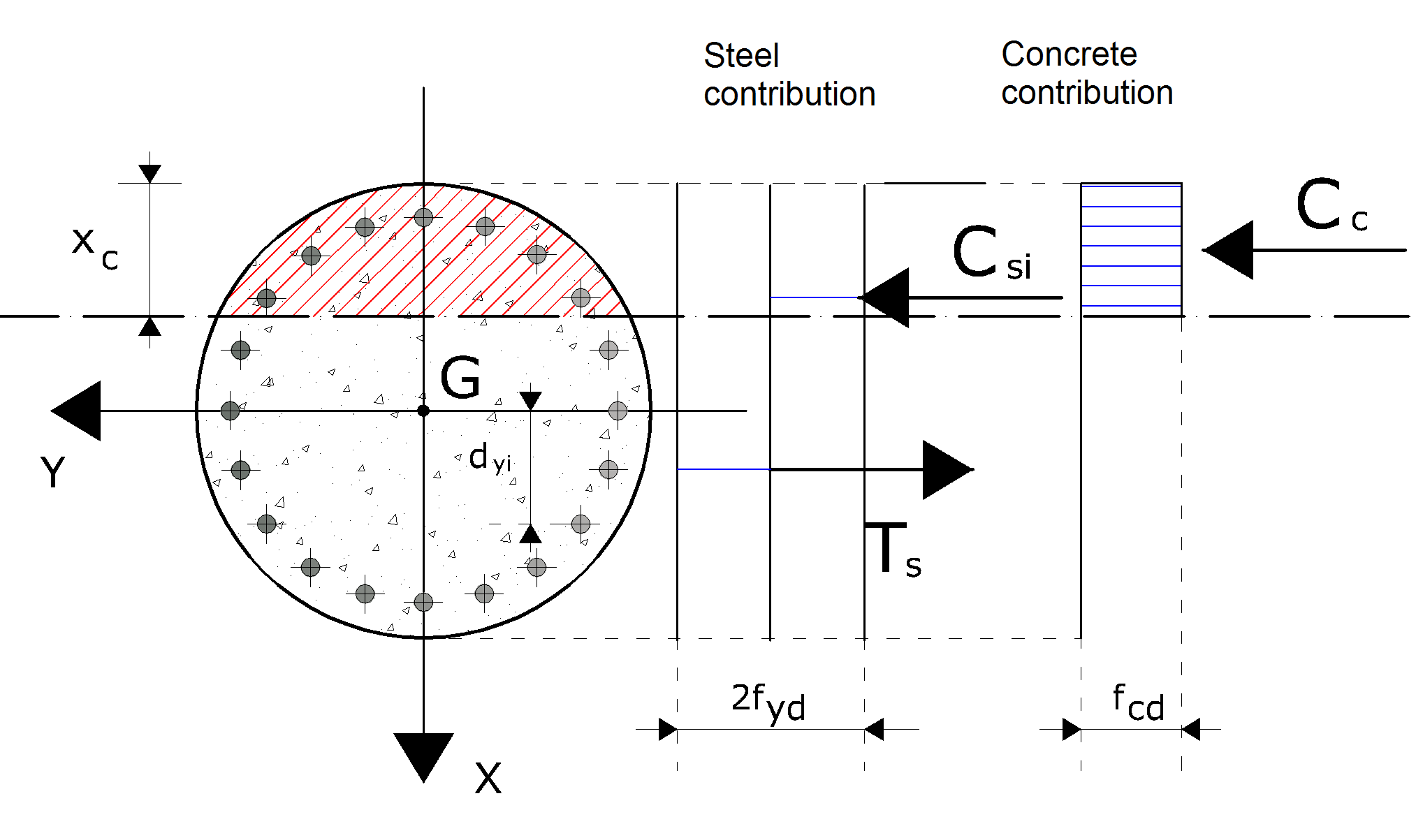
Diagram for the calculation of the field moment of a circular RC section
In this case, the value of the stresses – in correspondence of a preset depth of the neutral axis – is the following:
In the previous formulas, the symbols have the following meaning: