Unstructured mesh generation
The definition of the geometric model of the problem under examination, and the consequent generation of the calculation mesh (with triangular elements), can be carried out in the ways described below.
It should be recalled that the calculation mesh represents a discretisation of the geometric model under examination by means of a set of finite elements, each defined by nodes, at which the governing equations are solved.
To create the geometric model and generate the related calculation mesh, click on the "Unstructured mesh generation" button of the Home panel, which gives access to the following window.

Import from a dxf file
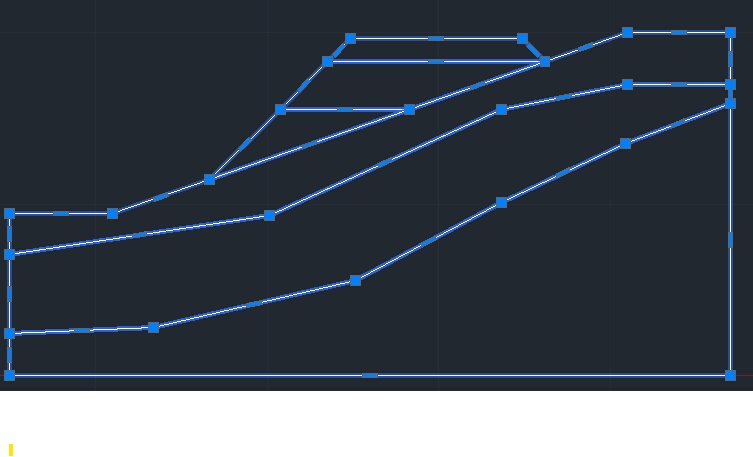
One of the most useful ways to define the geometric model of the problem under examination is undoubtedly to import into RSL III 2D the geometry previously defined in a CAD software and saved in dxf format. The dxf file to be imported must be suitably prepared, following the conventions described below:
- each soil layer considered is represented as a region, which must be defined by a closed polyline;
- the nodes of each closed polyline must be drawn from the bottom upwards, travelling along the polyline counter-clockwise.
The choice of the position of the reference system is arbitrary. The following image shows how to define the polylines in the CAD environment.
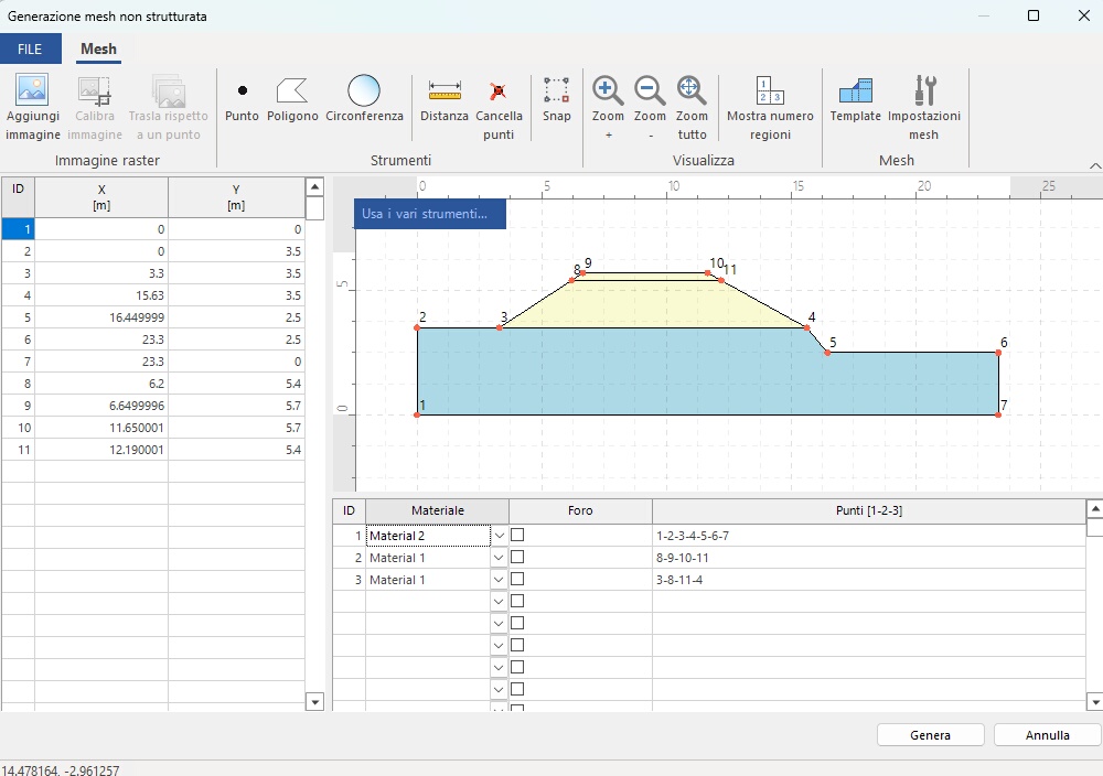
To import the geometry, click on File, then on Import, and then select the dxf file from the path where it was saved. The result of the import into RSL III 2D is shown below.
Import of coordinates (for example from a txt file or a spreadsheet)
If the coordinates of the region nodes are available, they can be imported into the relevant table on the left of the screen. The data to be imported must be organised in three columns, relative to the identification number, the X coordinate and the Y coordinate. After copying the data from the text file, they can be pasted into the table. The entered points are then displayed (see figure).
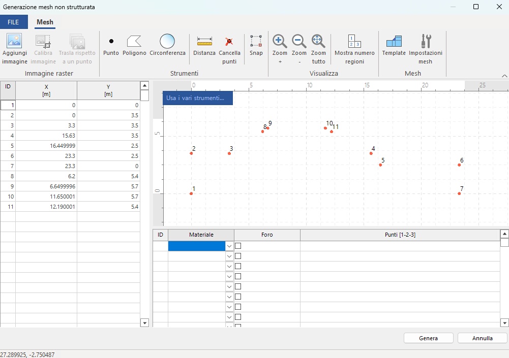
To define the regions it is then possible to join the relevant points by means of the Polygon command.
Definition by means of a template
By clicking on the Template button, you access the following window:
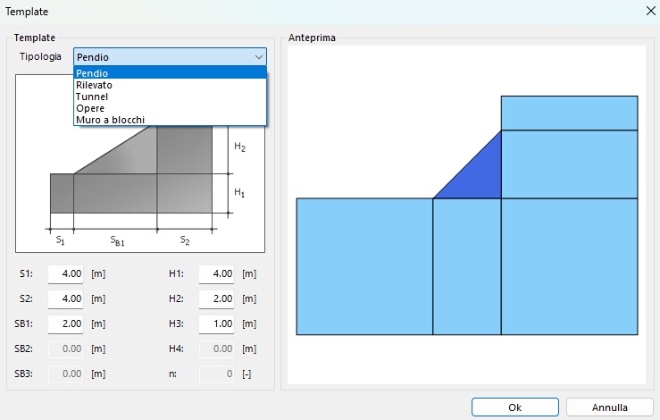
from which it is possible to define the geometry of various geotechnical works by filling in the required fields.
Manual drawing
Finally, it is possible to draw the mesh manually by means of the commands reported in the top bar.

Generation of the calculation mesh
After defining the geometric model, it is possible to proceed with the discretisation of the model into finite elements, generating the calculation mesh. From the "Mesh settings" button you access the following window:
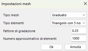
After defining the settings, click on OK and then on Generate. At the end of the generation process, click on Close to return to the main screen of the software. An example is reported below.

By means of the dedicated commands located at the top of the window shown, it is possible to refine the mesh or transform the elements into higher-order elements.