Buttress design: T-shaped cantilever and stem as a plate¶
This page describes how MDC calculates walls with buttresses (counterforts). The data (spacing, thickness, internal or external position) are entered as described in Buttresses; here we explain how the buttress and the stem are checked and reinforced.
In short:
- the external buttresses (downstream side, above the toe) are calculated as structural members;
- each buttress, together with the collaborating part of the stem, is an inverted T-shaped cantilever loaded by the actions of one spacing;
- the stem between two buttresses is a plate fixed at the base and on the buttresses, free at the top;
- the buttress reinforcement (bars along the inclined edge and web stirrups) is designed by the program and appears in the drawing, the bar schedule and the report.
Existing projects
This method replaces the equivalent-thickness method used in previous versions, which can no longer be selected. Projects with buttresses are recalculated with the new method: the stem reinforcement and the checks may differ from the results obtained in the past.
Why the old method was replaced¶
In previous versions, at each stem section, the T-section formed by the buttress (web) and the stem (flange of width equal to the spacing B) was replaced by a 1 m wide rectangle with the same centroidal moment of inertia:
and the reinforcement was designed on a 100 × heq section with the actions per metre. The procedure had three flaws:
- A stiffness equivalence used as a strength equivalence. Two sections with the same inertia do not have the same strength: lever arm, steel position and compression zone are different. With a 20 cm stem and 20 cm buttresses every 2.00 m, 1.80 m deep at the base, heq ≈ 109 cm: the reinforcement was calculated with the lever arm of a 109 cm deep section but placed in a 20 cm stem, on the unsafe side.
- The buttress was not reinforced. The buttress added stiffness but was neither checked nor reinforced as a member.
- Shear was checked on a 100 cm width, whereas the shear is carried by the buttress web (in the example 20 cm every 200 cm, i.e. 10 cm per metre).
In addition, the stem between the buttresses, which also bends horizontally, was not checked.
The internal forces of the cantilever (N, V, M per metre of wall) follow from equilibrium and do not depend on the stiffnesses: they are still those calculated by MDC with the cantilever wall calculation model. The new method changes the resisting section and adds the missing checks.
External and internal buttresses¶
External buttresses (downstream side). The buttress is a triangle above the toe: it rises along the downstream face over the full height of the stem and its free inclined edge descends to the end of the toe. Earth pressure stretches the upstream face of the stem and compresses the inclined edge: the buttress works as the compressed web of an inverted T and truly increases the lever arm of the internal forces. These are the buttresses calculated with the method described on this page.
Internal buttresses (upstream side, above the heel). They are not calculated as structural members. Their weight is considered (internal forces, global checks, foundation), but they do not contribute to the strength: the stem is checked as a cantilever without buttresses, with its real thickness. The report states this. To calculate the buttress as a structural member, use external buttresses or a dedicated model.
Weight and seismic inertia of the buttress¶
The buttress weight is calculated with the unit weight of the wall material and the same partial factor as the self-weight of the wall in the combination. In seismic combinations the horizontal inertia force kh·W is added.
- In the global checks (overturning, sliding, bearing capacity) and in the actions on the foundation and on the piles, the buttress weight and its inertia act as a load per metre of wall, W/i, applied at the centroid of the buttress.
- In the stem sections the buttress weight is not added to the loads per metre: it enters the T-section check, section by section, with only the part of the buttress above the section.
The inverted T-shaped cantilever¶
Section geometry¶
At each calculation section of the stem, at level z, the resisting section is an inverted T made of:
- web: the buttress, of width bw (buttress thickness) and depth varying with the level, from the inclined edge to the downstream face of the stem;
- flange: the stem, of thickness s (variable with the level if the stem is tapered) and effective width beff.
The total depth of the section hT(z) goes from the inclined edge to the upstream face of the stem. The effective depth is
where c is the distance of the centroid of the upstream vertical bars from the upstream face of the stem. This is where the buttress really helps: at the base d is of the order of the toe length, not of the stem thickness.
Effective width of the flange¶
The width of the flange that works with the web is calculated with the rule of Eurocode 2, §5.3.2.1 (the same as in the Italian NTC Commentary), taking the buttress height as the distance between points of zero moment, l0 = Hc (cantilever without adjacent span):
where i is the buttress spacing and bw their thickness. Taking l0 = Hc (instead of 2 Hc) is on the safe side. beff is calculated by the program, not entered, and is printed in the report.
Example: spacing 2.00 m, 0.20 m buttress, bi = 0.90 m.
| Buttress height | beff,i | beff |
|---|---|---|
| 2.50 m | min(0.43; 0.50; 0.90) = 0.43 m | 1.06 m |
| 6.00 m | min(0.78; 1.20; 0.90) = 0.78 m | 1.76 m |
Actions on the T¶
MDC calculates the stem internal forces per metre of wall: axial force N, shear V and moment M. The T carries the actions of one spacing, plus the weight W(z) of the part of the buttress above the section and, in seismic conditions, its inertia:
where (xg, yg) is the centroid of the part of the buttress above level z and xb the abscissa of the stem axis at that level. The moment is positive when it stretches the upstream face of the stem (usual case, earth pressure). If the moment changes sign in some section, the section is checked upside down: the inclined edge and its bars are in tension, the flange in compression.
Section materials¶
- Compressed concrete: the web (inclined edge side) and, if the neutral axis reaches it, the flange; concrete in tension is ignored.
- Tension steel: the upstream vertical bars of the stem within the effective width. With a reinforcement as,up per metre:
Only the bars within beff count as T reinforcement (EC2 §9.2.1.2).
- The downstream vertical bars of the stem within beff and the bars along the inclined edge of the buttress complete the section; the edge bars are considered with their inclination.
Checks of the T-section¶
Bending with axial force at ULS¶
The N-M check uses the same method as the generic section of RC-SEC: the section is divided into strips, concrete follows the parabola-rectangle law (εc2 = 2‰, εcu = 3.5‰) and steel the elastic-perfectly plastic law with ultimate strain εud. The failure configurations are those with pivots A, B, C (EC2 fig. 6.1, NTC 2018 §4.1.2.3.4). For the design axial force NT the neutral axis is found by bisection and the resisting moment is obtained; the check is
Shear on the web¶
Shear is carried by the buttress web, of width bw and effective depth d, according to NTC 2018 §4.1.2.3.5 (same formulas as EC2 §6.2).
Without shear reinforcement (§4.1.2.3.5.1):
with k = 1 + (200/d)1/2 ≤ 2 (d in mm), vmin = 0.035 k3/2 fck1/2, ρl = As,T / (bw d) ≤ 0.02 and σcp = NT / Ac.
With web stirrups (§4.1.2.3.5.2), two-leg stirrups of area Asw at spacing s:
with ν = 0.5 and αc depending on the mean compression σcp. The strut inclination is chosen with 1 ≤ cot θ ≤ 2.5: it starts from cot θ = 2.5 and, if the reinforcement is stronger than the struts, the value of cot θ that makes the two resistances equal is used. The resistance is
The vertical component of the force in the inclined compressed edge reduces the shear in the web: it is favourable and is neglected, on the safe side.
Shear between flange and web¶
The tension in the flange bars increases towards the base; the part outside the web must be transferred to the web by shear through the stem (EC2 §6.2.4). Between two consecutive sections, at a distance Δx, the change of the flange force on each side is
and the shear stress at the flange-web junction, of thickness s:
- Strut crushing (θf = 45°): vEd ≤ ν fcd sin θf cos θf = 0.5 ν fcd, with ν = 0.6 (1 − fck/250). If not satisfied, the program asks to increase the stem thickness.
- If vEd ≤ 0.4 fctd no additional reinforcement is needed.
- Otherwise the horizontal transverse reinforcement, total on both faces, is
The stem also bends horizontally as a plate (see below). According to EC2 §6.2.4(5), on each face the larger of half the transverse reinforcement and a quarter of it plus the reinforcement required by the panel bending is provided:
Buckling of the free compressed edge¶
The external buttress is a thin plate, supported by the stem, with a compressed free inclined edge. Its stability is checked as plate buckling with one free edge, with maximum compression at the free edge and zero at the stem:
with k = 1.70 (EN 1993-1-5, table 4.2), Eeff = Ecm / (1 + φ) = Ecm/3 (creep with φ = 2), ν = 0.2, t = buttress thickness, b = length of the buttress at the base. The check is satisfied if
(in allowable stress projects the comparison is with 2 σ̄c). If it is not, the program asks to increase the buttress thickness.
Serviceability checks (SLS)¶
Stresses are calculated on the cracked T-section (concrete not resisting tension, modular ratio n = 15) and compared with the NTC 2018 §4.1.2.2.5 limits:
- concrete: σc ≤ 0.60 fck in the characteristic (rare) combination and, conservatively, also in the frequent combination; σc ≤ 0.45 fck in the quasi-permanent combination;
- steel: σs ≤ 0.80 fyk in the characteristic combination.
The crack width of the tension flange (frequent and quasi-permanent combinations) is calculated with EC2 §7.3.4:
with kt = 0.4, k1 = 0.8, k2 = 1.0 (on the safe side), αe = Es/Ecm, ρp,eff = As,T / (beff hc,ef) and hc,ef = min(2.5 (c + φ/2); s/2). The limits are those of NTC 2018 table 4.1.IV for low-sensitivity reinforcement:
| Environmental conditions | Frequent | Quasi-permanent |
|---|---|---|
| Ordinary | 0.4 mm | 0.3 mm |
| Aggressive | 0.3 mm | 0.2 mm |
| Very aggressive | 0.2 mm | 0.2 mm |
Allowable stresses¶
If the project uses allowable stresses (Italian D.M. 14/02/1992) the T-section is checked with the elastic calculation (modular ratio of the project) and the stresses are compared with σ̄c and σ̄s. Web shear is checked with τ = VT / (0.9 d bw) and the values of the Italian D.M. 1996 (kg/cm²):
If τ ≤ τc0 no calculated stirrups are needed; if τc0 < τ ≤ τc1 the web stirrups are designed with σ̄s for the whole shear; if τ > τc1 the section is insufficient and the buttress thickness must be increased.
The stem between two buttresses¶
Between two buttresses the stem bends both vertically and horizontally. MDC calculates it as a linear elastic (Kirchhoff) plate, analysed with finite elements:
- rectangular panel with width equal to the clear span between the buttresses, Lx = i − bw, and height equal to that of the buttress;
- thickness equal to the mean stem thickness, elastic modulus Ecm, Poisson's ratio 0.2;
- regular 16 × 16 mesh of 4-node rectangular elements with 12 degrees of freedom (displacement and two rotations per node);
- restraints: fixed at the base, fixed on both buttresses (exact by symmetry for inner panels with constant spacing), free top edge;
- load: the horizontal pressure p(z) obtained, level by level, from the change of the shear per metre calculated by MDC; it therefore includes earth pressure, surcharges, water and seismic actions of the combination.
The plate moments (mx horizontal, my vertical, mxy twisting) give the reinforcement, with as = m / (0.9 d fyd) (σ̄s with allowable stresses):
| Reinforcement | Moment | Where |
|---|---|---|
| Horizontal, upstream face | mx at the fixed edges on the buttresses | supports |
| Horizontal, downstream face | mx + |mxy| at mid-span | span |
| Vertical, upstream face | −my + |mxy| (maximum across the width, at each level) | especially at the base |
The horizontal reinforcement obtained in this way, combined with the flange-web shear reinforcement as described above, sets the spacing of the stem distribution bars.
The upstream vertical reinforcement of the stem must satisfy both checks, which concern different members (the T as a whole and the local bending of the panel):
Both checks are made with the full load. No plastic redistribution is considered: the plate moments are taken as they result from the elastic analysis.
Buttress reinforcement¶
The reinforcement is designed by the program over all ULS combinations:
- Upstream vertical bars of the stem: at each section the number of bars per metre is increased until the T is verified in all combinations and the reinforcement is not less than that required by the plate; if this is not enough, the next bar diameter is used.
- Bars along the inclined edge of the buttress: normally 2 bars with diameter not less than 16 mm nor than the stem bars; number and diameter increase if in some section the moment stretches the edge.
-
Horizontal two-leg web stirrups: the area is the larger of that required by shear and the NTC minimum (§4.1.6.1.1)
\[A_{st,min} = 1.5\, b_w \quad \text{(mm}^2\text{/m, with } b_w \text{ in mm)}\]with spacing not greater than 0.8 d (and 33 cm); if the spacing becomes too small the diameter is increased.
-
Stem distribution bars: the spacing is reduced if the plate or the flange-web shear require it; if a spacing below 10 cm would be needed the program asks to increase the diameter.
Edge bars, web stirrups and stem reinforcement appear in the drawing, in the bar schedule and in the calculation report, which also gives the effective width, the actions on the T and the checks section by section, the plate results and any warnings.
Warnings¶
At the end of the calculation the program reports, among others:
- T-section not verified even with the maximum reinforcement → increase the buttress or stem thickness, or reduce the spacing;
- shear greater than the web strut resistance → increase the buttress thickness;
- crushed struts in the flange-web shear → increase the stem thickness;
- possible buckling of the free compressed edge → increase the buttress thickness;
- shear, stresses or cracks not verified in a combination, with the level of the section.
Views of the wall with buttresses¶
Besides the cross-section, a wall with buttresses is checked with three dedicated views, chosen from the CALCULATE › Views group (buttons or the Views list).
Elevation¶
The Elevation button shows the wall seen from downhill, with dimensions: total length, buttress spacing, thickness, stem and foundation heights and, for walls on piles, the row of piles with their spacing. Buttresses are evenly spaced, with the first and last flush with the ends. The elevation does not require the calculation. The length is the one set in Geometric data.
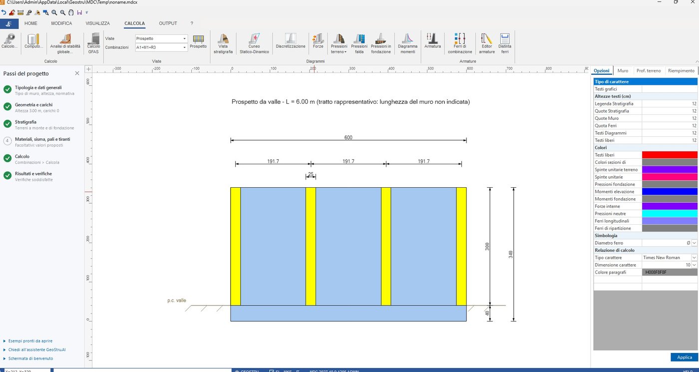
In Geometric data a warning appears when the buttresses do not fall above the piles (buttress spacing not a multiple of the pile spacing, or an offset caused by the wall length) and, with one click, proposes the value that aligns them.
Stem stresses¶
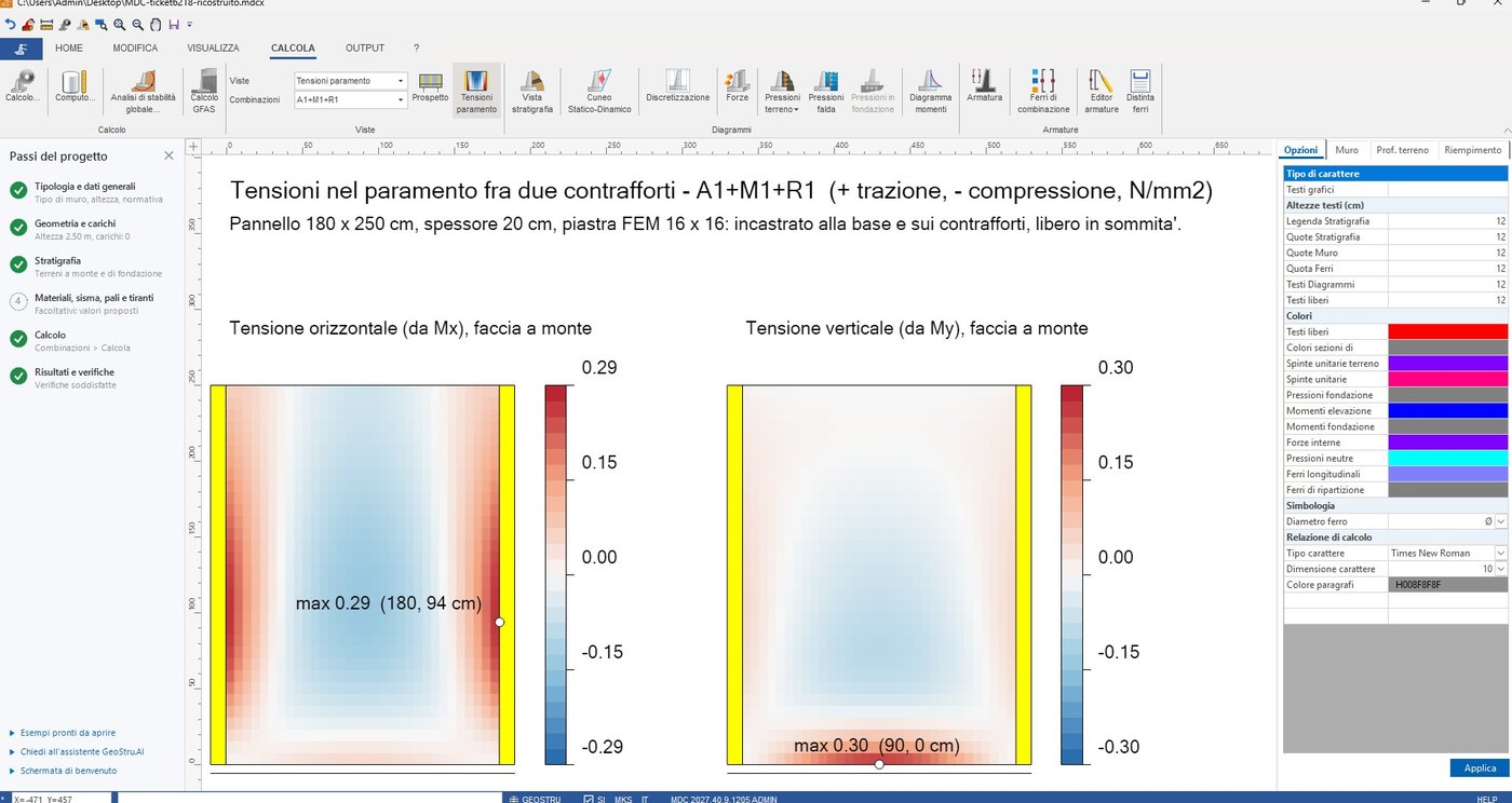
The Stem stresses button shows, for the combination selected in the bar, the bending stresses on the uphill face of the panel between two buttresses, obtained from the finite element plate:
- on the left the horizontal stress (from mx), which governs the distribution bars; the maximum is usually next to the buttresses;
- on the right the vertical stress (from my), which governs the uphill vertical bars; the maximum is usually at the base, mid-panel.
The scale goes from blue (compression) to red (tension); the point of maximum tension is marked with its value and position. The view is available after the calculation and only with external buttresses: without buttresses the button is disabled.
Reinforcement and safety factors¶
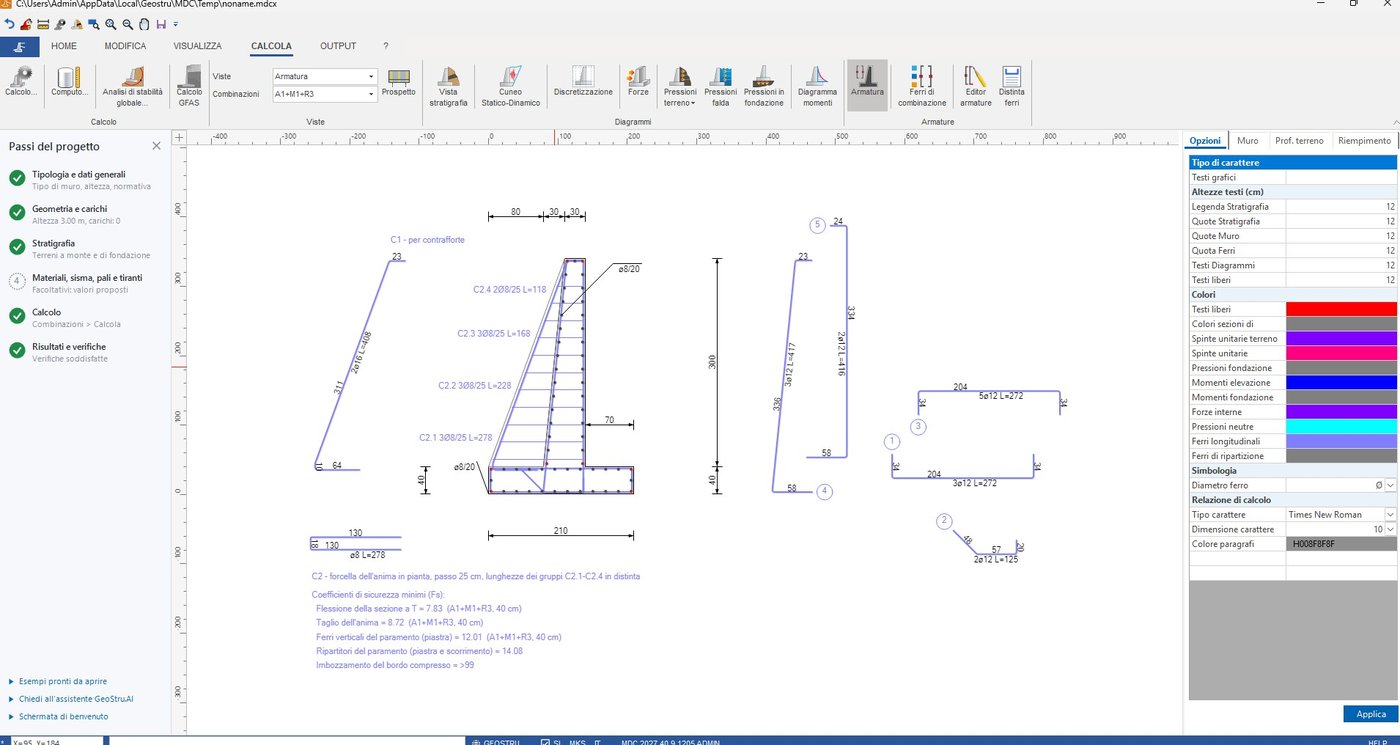
The Reinforcement view draws the buttress with the bars along the inclined edge and the web links, with the dimensioned bar shapes (they can be dragged with the mouse; their position is saved in the file). Below the drawing the minimum safety factors are listed (T-section bending, web shear, stem vertical and distribution bars, buckling) with the combination and height where they occur.
The 3D View (VIEW › 3D View) shows wall, buttresses, reinforcement, stratigraphy and piles over the length set in the window.
Limits of the method¶
- End panels (the last panel, with one free side) are not treated separately: all panels are calculated as inner panels, fixed on both buttresses.
- The foundation is calculated as before: the toe is checked as a cantilever in 1 m strips, ignoring the support provided by the buttresses, which is on the safe side. The actions on soil and piles are those per metre of wall.
- The buttress always occupies the full height of the stem and the full length of the toe; shorter or lower buttresses cannot be entered.
- Internal buttresses are not calculated as structural members (see above).