Formulation of the element matrices and vectors for elasticity problem > A General Formula for the Stiffness Matrix
Consider a linearly elastic body that caries conservative load. Let its volume be V and its surface area be S. The expression for the potential energy in a linearly elastic body is:
 |
(14) |
in which

represents the displacement field;

represents the strain field;

the elastic constants matrix (material property)

,
initial strains and initial stresses;

body forces;

surface tractions;

represents the nodal d.o.f. displacements

loads applied directly to d.o.f.
Displacements within an element are interpolated from element nodal d.o.f. d as:
 |
(15) |
where N is the shape function matrix.
Strains are obtained from displacements by differentiation.
 |
(16) |
where
 |
(17) |
and represents the strain-displacement operator. The differential operator matrix 
is given in the case of the plane problems as:
 |
(18) |
Substitution of the expressions for 
and 
into Eq. 14 yields:
 |
(19) |
where summation symbols indicate the we include contribution from all finite elements of the structure, and the element stiffness matrix and element equivalent nodal loads vector are defined as:
 |
(20) |
 |
(21) |
where Ve denotes the volume of an element and Se its surface and in the surface integral the shape function matrix is evaluated on Se.
Every degree of freedom in an element displacement vector d also appears in the vector of global structural d.o.f. D. Therefore D can replace d in Equation (14) if k and re of every element are conceptually expanded to structure size. Thus Eq.(14) becomes:
 |
(22) |
where
 |
(23) |
represents the global stiffness matrix and nodal force vector expanded in global coordinates at structure level. In the Eq.(22) the summation operator indicate the assembly of elelemnt matrices and vectors.
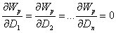
This way the total potential Wp of the structure is represented as a function of d.o.f. D. Making Wp stationary with respect to small changes in the vector D we can write:
 |
(24) |
or explicitly:
 |
(25) |
yielding the following simultaneous algebraic equations to be solved for n unknowns representing the displacements collected for each d.o.f. of vector D:
 |
(26) |
where n represents the number of total d.o.f. of structure, K and R represents the global stiffness matrix and nodal loads vector assembled for the entire structure.
© GeoStru Software