Upstream toe works and downstream face reinforcements
The Works tab completes the embankment section with three elements, each one switched on by its Present check box:
- A - Riprap foundation at the upstream toe: a block of cyclopean boulders (for example granite) below the base level, in front of the upstream toe;
- B - Riprap toe on the upstream face: flat boulders laid on the upstream face, with their base on the base level;
- Downstream face reinforcements: horizontal geogrids (or geotextiles, steel meshes) wrapped around the face.
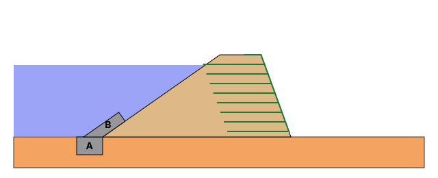
The elements that are present appear in the section drawing (layer OPERE), in the 3D view and in
the calculation report, and are saved in the .esd file. Files created with earlier versions open without works.
A - Riprap foundation
| Data | Meaning |
|---|---|
| Width [m] | horizontal size of the block |
| Height [m] | thickness below the base level (the top of the block is on the base level) |
| Distance from the upstream toe [m] | distance, towards upstream, between the upstream toe and the downstream side of the block (0 = in contact) |
| Unit weight [kN/m³] | weight of the boulder block, voids included |
| Base friction angle [°] | friction between the block and the foundation soil |
| Permeability Ko, Kv [m/s] | horizontal and vertical permeability of the boulders, for the seepage analysis (new projects 1·10-9, concrete blocks; dry boulders about 1·10-2) |
B - Riprap toe
| Data | Meaning |
|---|---|
| Length along the face [m] | extent of the toe along the upstream face, from the toe upwards |
| Thickness [m] | boulder thickness, normal to the face |
| Unit weight [kN/m³] | weight of the toe, voids included |
| Shear resistance angle [°] | of the boulders, used as a material in Slope |
| Permeability Ko, Kv [m/s] | horizontal and vertical permeability of the boulders, for the seepage analysis (new projects 1·10-9; dry boulders about 1·10-2) |
The toe is a parallelogram: its inner side lies on the upstream face, its base on the base level.
Effect on the sliding checks
Foundation and toe act as a toe buttress for the upstream part of the embankment. In the checks where the upstream face is pushed towards the reservoir, the resistance Rm increases by:
ΔRm = WB·tanφ' + WA·tanφA
where WB = LB·sB·γB is the weight of the toe, φ' the shear resistance angle of the dam body, WA = bA·hA·γA the weight of the foundation and φA the friction angle at its base.
| Check | Contribution of the works |
|---|---|
| Full reservoir | none: the thrust is towards downstream |
| Empty reservoir | ΔRm with the weights γA, γB |
| Rapid drawdown | ΔRm with the buoyant weights γ − γw, like the soil (γg) |
The passive resistance of the soil in front of the foundation is neglected (on the safe side). In the Checks tab the resisting action includes the contribution; it is also shown in the row of which upstream toe works (visible only when present); the report shows it separately. See Verification.
Effect on seepage
The foundation and the toe enter the finite element seepage analysis as materials with their own Ko and Kv permeabilities: they change the flow net, the phreatic line, the discharge, the uplift and the piping safety factor. The foundation lies inside foundation layer 1 (limited to its thickness) and counts only if layer 1 is permeable.
- Dry boulders (k ≈ 10-2 m/s): the reservoir water reaches the downstream side of the foundation almost without head loss and the seepage path gets shorter: discharge and uplift increase, the piping safety factor decreases.
- Clogged or mortared boulders (very low k): the water flows under or around the foundation and the path gets longer: discharge and uplift decrease, the piping safety factor increases.
The effect is stronger the less permeable the embankment and the foundation soil are compared with the boulders.
Why water flows under an impervious foundation
Foundation A occupies only the upper part of foundation layer 1. Even if it is impervious, the water enters from the reservoir bottom upstream of the block and flows under it, through the part of layer 1 between the block and the impervious layer; the block lengthens the path but does not cut it. To stop the flow in the foundation a cut-off wall or sheet pile reaching the impervious layer is needed.
Downstream face reinforcements
| Data | Meaning |
|---|---|
| Number of layers | number of reinforcement layers |
| Elevation of the first layer [m] | elevation of the first layer above the base level |
| Vertical spacing (facing height) [m] | distance between two layers; it is also the height of the wrap on the face |
| Length into the embankment [m] | horizontal length from the face inwards |
| Wrap-around length [m] | horizontal part of the wrap, above the facing |
| Type | geogrid, geotextile or steel mesh |
| Design tensile strength [kN/m] | allowable strength of the reinforcement (Tallow) |
| Soil-reinforcement friction angle [°] | interface friction, for the pullout resistance |
| Pullout coefficient [-] | pullout coefficient Fb |
| Colour, Line thickness [px] | how the reinforcements are drawn (the colour also in the 3D view and in Slope) |
Layers above the crest are not generated; the last wrap stops at the crest.
Reinforcements are not used in the ESD checks
Reinforcements do not change the ESD sliding or hydraulic checks. The stability of the facing and the global stability are checked in Slope: with the Slope button the reinforcements are exported as reinforcement elements (not as reinforced earth), with length, facing height, wrap, face inclination, Tallow, friction and pullout coefficient. In Slope each reinforcement crossed by the slip surface resists with the smaller of Tallow and the pullout resistance of the part beyond the surface. See Global stability Analysis.
Foundation and toe in Slope
With the Slope button the foundation and the toe are exported as separate materials (c = 0, φ and γ of the boulders; permeable if the higher permeability is at least 1·10-7 m/s, otherwise impervious):
- the toe is layer 1: the ground profile runs over it;
- the foundation is a layer between the dam body and the first foundation layer, going below the base level only under the block (not deeper than the first foundation layer).
In this way the slip surfaces crossing the upstream toe take the resistance of the boulders into account.
Downstream ground: extent and ground level
In the Geometry tab:
- Downstream extent from the toe [m]: length of the ground downstream of the toe up to the end of the section (for example a wall or a building 60 m away). 0 = automatic (15% of the section width). It applies to the drawing, the foundation layers, the flow net, the 3D view and the profile exported to Slope.
- Ground level position (Y): depth of the downstream ground measured from the crest downwards. The downstream toe is buried and the downstream ground reaches that level (filled in the drawing). 0 = downstream ground at base level. It is used in the drawing, the 3D view and Slope, not in the sliding checks.
- Foundation level a.s.l. [m]: absolute level of the foundation, which is the zero of the drawing. It is only used to show the levels above sea level: in the drawing next to the maximum reservoir level and the bottom of the sheet pile wall (for example "y = 3.99 m (+18.99 a.s.l.)"), in the report for foundation, maximum reservoir level, crest, top and bottom of the sheet pile wall. It does not change the calculations. 0 = not given.
© Geostru